All because of the strong rise of Chinese bearings?Famous Japanese enterprises were exposed to brand scandal, European and American enterprises suffered cheating
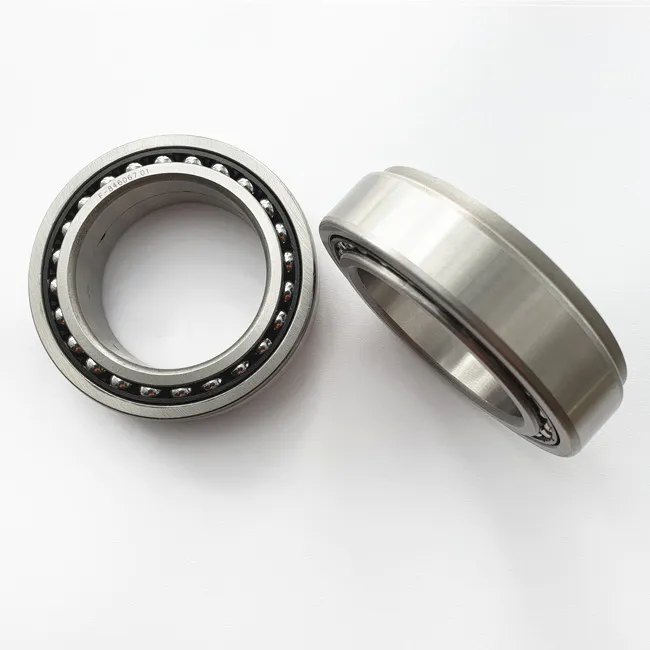
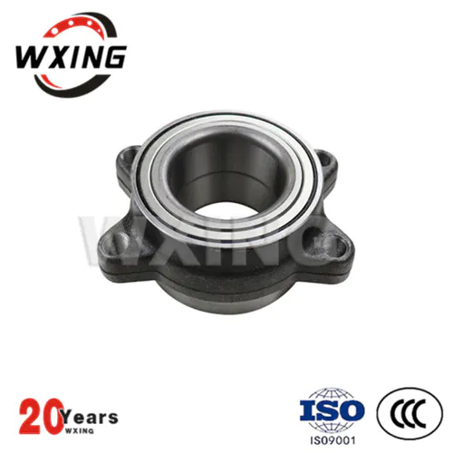
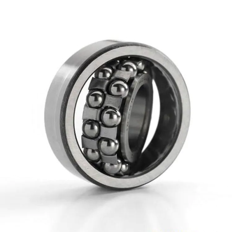
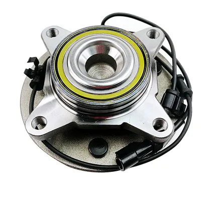
As a manufacturing powerhouse, Japan fraud scandals are now flying, kobe steel fraud not only, even Japan has also been known to expose the branded scandal, staged an civet cats in farce of the prince, the company is Japan tsubaki island, is mainly responsible for bearing components and finished goods production, but due to limited capacity, tsubaki island can't satisfy foreign orders,And do not want to lose the good opportunity to make money, so directly purchase Chinese bearing parts, and then paste the brand to earn the price difference, European and American enterprises were cheated, after the story was revealed, the Japanese enterprise also blamed, all because of the strong rise of Chinese bearings.