The CA6140 lathe I shaft assembly process analysis
The CA6140 lathe I shaft assembly process analysis
by:Waxing2020-11-13
I CA6140 lathe 2019 - shaft assembly process analysis
12 -
14 in ray bin-bin zhu Wu Gui (
Jinhua technician college)
Abstract: the work of CA6140I axis orientation, clear assembly technology requirements, the analysis of the structure, to complete the assembly process.
Key words: I shaft;
Structure;
Process;
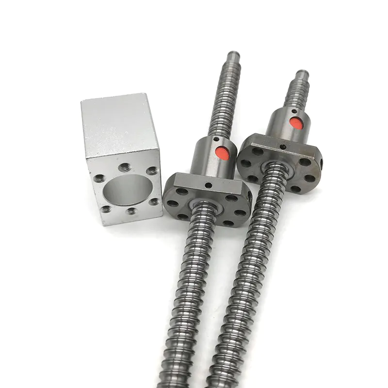
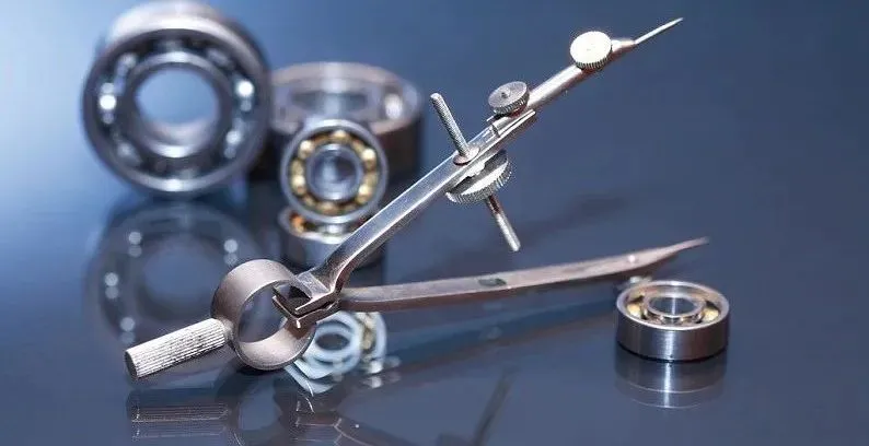
I shaft assembly 1 ca6140 lathe work I introduce lathe axis on the lathe of the transmission system plays an important role, it passed through the belt of the torque of the motor and rotary motion is passed on to the main shaft, and through the lever control spindle and reversing.
The spindle assembly quality directly affect the transmission system operation.
Lathe axis I at work because of friction to produce a lot of heat, so the oil cooling should be used when working.
2 ca6140 lathe I shaft assembly technology requirements of axial channeling move & le;
0.
3 I ca6140 lathe axis structure analysis works: pull the fork 13 drive pressure ring around 10 mobile, pressure ring mobile make wing pin short cylindrical pin swinging around 11.
When wing pin 9 swinging rod will be to the right wing pin to the left, pressed ahead friction plate tightly, through the friction lining, transfer torque to dual gear, which drives the duplex gear rotation, when the lathe spindle rotation.
When swinging rod 9 left wing pin will be pushed to the right wing pin, putting the car friction pressure, thus promote single gear running, then car spindle inversion.
When pressure ring moved to the middle position, on the left to the right of the friction plate is in loosen condition, torque transfer out, spindle stop running.
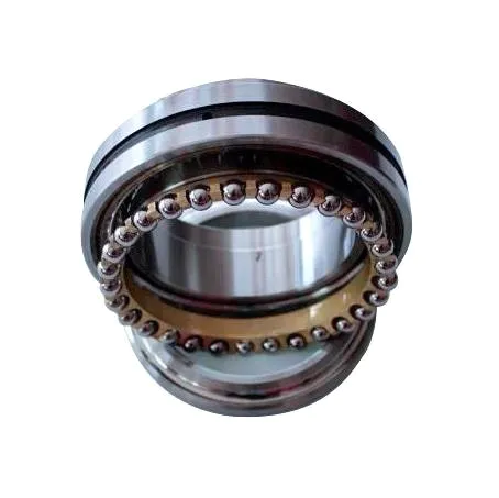
I CA6140 lathe axis is more classic friction clutch structure, assembly when the key is to ensure that the axial momentum, the clutch friction plate elastic to adjust properly.
4 assembly system diagram of CA6140 lathe I shaft assembly step 1: remove burrs on the parts and parts cleaning.
Step 2: install the spline sliding sleeve.
Will slide a condom on the spline, the sliding sleeve hole on the waist on the shaft alignment hole, at the same time at the end of the tie rod hole alignment holes in sliding sleeve (
Three holes aligned)
。
Wear the pin into the three holes.
Step 3: installing and adjusting nut.
First put a spring in the sliding sleeve hole, the rotating adjusting nut positioning pin card into the card slot on the adjusting nut.
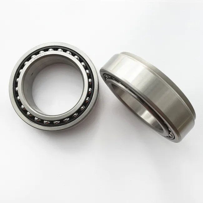
Step 4: install forward friction plate.
In one end of the thread, in accordance with the first a internal friction slices, put a outside the order of the friction plate, loading internal friction piece 8 piece, external friction 7 pills.
Step 5: installing spline localizer.
First location ring pack, the grooves on the spline 30 & rotating deg;
, let its stuck spline flange, then load the positioning ring, and the screw fastening.
Step 6: reverse friction piece and locating piece installation.
At the other end of the shaft, according to the first one internal friction slices, put a outside the order of the friction plate, loading internal friction piece 6 piece, external friction slices of 5 pieces.
The installation of the positioning piece with step 5.
Step 7: installation of single and double gears.
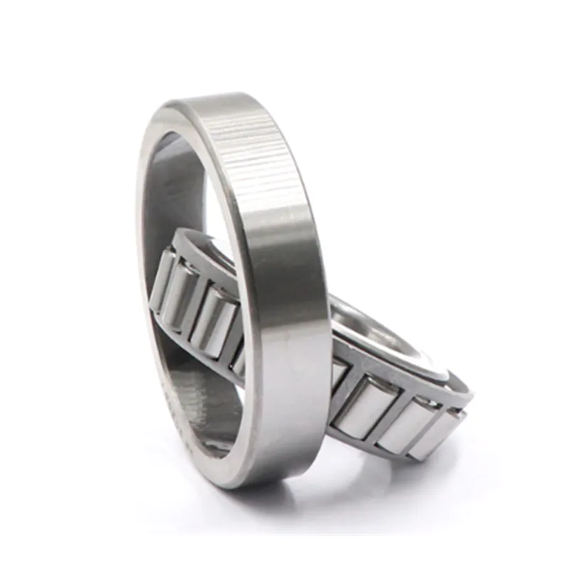
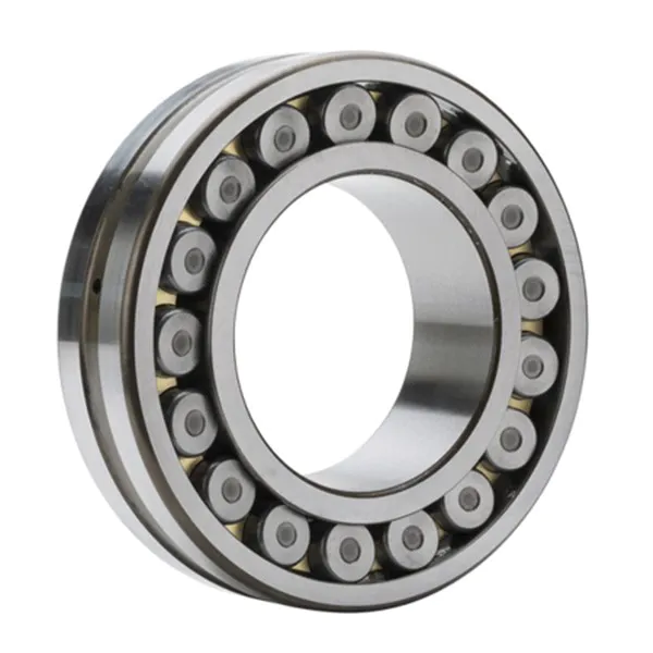
Two in the rolling bearing in gear shaft sleeve as shown in figure, then aim the gear on the edge of the gap, friction plate flange, and put into gear.
Step 8 installation sleeve bearing and retainer.
First fill and load bearing, shaft sleeve, with the spring calipers, finally the spring collar into shaft in the card slot.
Step 9: install flat key.
The changping keys into the keyway.
Step 10: wing key installation.
Wing key to be included in the bar slot, wear into the cylindrical pin.
Step 11: installation of pressure ring.
Pressure ring set on the shaft, on the wing.
Adjust the friction plate to right position, so that the pressure ring around mobile compaction friction plate.
Steps as shown in figure 4.
References [
1]
Xu Bing editor.
Mechanical assembly technology [
M]
。
China light industry press, 2010.
(
2]
Chang Hong editor, bearing industry association, China human resources staff education work committee compile for universal use.
Bearing assembly process [
M]
。
Henan people's publishing house, 2006.
Source: the 'silicon valley'