Vertical mill hydraulic line leak solution - 2019
07 -
02 mornay hubei just (
Tangshan Jidong Equipment Engineering Co. , ltd. Equipment research and development center)
0, preface my company independent research and development of JLMS54 final powder cement vertical roller mill the installed power of 4200 kw, in June 2012 formally in jidong cement younge companies since the operation of production line PC42.
5 cement output remain above 200 t/h, than table for 3600 & plusmn;
100c㎡/g。
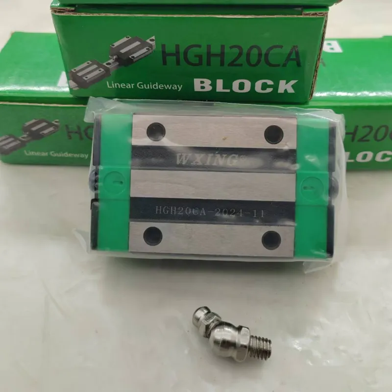
The vertical mill at the beginning of the run there is a problem, namely, equipment operation, less than a week points of tubing in the hydraulic system and hydraulic cylinder joint surface (
As shown in figure 1 A)
Appear leak phenomenon, since each leak leakage loss of oil product is more, down time is longer, seriously affected the normal production operation of the vertical mill.
So this article mainly aims at the seal failure and A damage problem, reason analysis, and put forward solutions.
1, reason analysis diagram 1 shows as the connecting line between the hydraulic cylinder and accumulator, for realizing the rapid and fill pressure accumulator for hydraulic cylinder cushion, A design of large diameter pipeline interface, shown in figure 1 A form of the original seal as shown in the figure 2.
In figure 2 points tubing high-pressure hose are connected at one end, and the other end of the 1 welding flanges, the flange 1 and hydraulic cylinder flange connected by bolts, two flange is to use a face o-rings (
Figure 2 seal (1)
Seal.
Appear early leak, we suspect is that the poor quality of o-rings and o-rings installed is not standard.
Take in the replacement of high quality imported sealing ring, improved measures after the installation process, vertical mill run normally only for a few days, o-rings again damage.
Therefore, we need further analysis of the problems for other reasons.
Connection between hydraulic cylinder and fixed the tubing of high pressure hose in high pressure hydraulic system (
Usually around 12 mpa)
, will produce larger outside line tension.
Hydraulic cylinder work do small frequent swinging around the bottom pin, under the effect of the pull of the line tension, the points of the tubing flange 1 combined with hydraulic cylinder flange surface of end face sealing form (
Figure 2 seal (1)
It is easy to failure cause oil leakage.
Vertical mill vibration caused by shock at the same time, the two flange bolts to loosen, failed to tighten when if become loose, also increase the chances of A place to leakage of hydraulic oil.
2, 1 original solution on reservation flange end face seal (
The seal (1)
On the basis of adding a runs along the axial seal (
The seal (2)
The flange to take over, see figure 3.
The specific technical measures are as follows: 1)
First expand the flange and the hydraulic cylinder flange connection of the inner hole 1, the same points and the diameter of the tubing diameter, bore hole need to make sure that when you bore reaches certain cylindricity and vertical degree requirements.
Then within one cavity flange welding a flange, the flange to take over the small end part runs and type O sealing ring size matching axial sealing groove (
Two of the original transverse and axial seal groove in two dimensions and processing requirements 'mechanical design manual' for reference in this no longer give details)
, and the small diameter and hydraulic cylinder flange diameter, can guarantee two joint surface with compaction, big end diameter smaller than the inner diameter of the flange 1 new reaming 1 ~ 3 mm, in order to load the flange to take over.
The flange to take over the conveniently, can use ordinary steel tube, made simple.
2)
To ensure the flange to take over the axial sealing to achieve good sealing effect, in addition to the flange 1 requirement of inner hole as part of the cylindricity and vertical degree requirements, and can have a set of relatively complete installation process.
Because needs to be done on the spot welding flange pipe and flange 1 work, lead to the flange to take over and hydraulic cylinder flange alignment is difficult to ensure, so we design the special welding positioning tools to complete the installation work.
The positioning tool according to the principle of locating at six limit five degrees of freedom, there is no limit to the only along the axis of rotation degrees of freedom.
The positioning tool available to ordinary steel plate, the center opened a similar triangle spline slotting shape hole, opened four round hole edge, its shape, location, size and the fastening of the flange 1 four round hole are exactly the same, as shown in figure 5.
Implementation prior to welding the flange to take over the pressure into the flange again after 1 lumen to the specified location will locate tools through the flange to take over the small end of the part, with flange after adjust position 1 originally equipped with the positioning tool with flange bolts to hold 1.
Then leave good three cavity on the positioning tool has implemented three discontinuous welding, thus finished the installation of the flange to take over the job.
As shown in figure 4.
Hydraulic piping installation again, in the process of vertical mill operation to strengthen inspection, regular inspection, to prevent the bolt is loose.
3, the use effect of the improved hydraulic line, after nearly more than 1 months of follow-up, and no leakage occurred, vertical mill running effect is good, the double seal structure effectively adapt to the complex business environment.
Source: 'sichuan cement'