CONTACT US
Zhejiang waxing electromechanical co.LTD.,Factory located in Shandong,Headquarters located in Zhejiang,China.
1. Purpose of electrically insulating bearings
The so-called electrically insulating bearing is also an insulating bearing, and the electrically insulating bearing includes all rolling bearings that can prevent the passage of current. Bearings with ceramic coatings on both the inner and outer rings are called insulated bearings. The ceramic coating prevents the passage of electric current and has insulating ability.
The rolling elements of hybrid bearings are made of ceramic and therefore also have insulating capabilities. It is made of rolling elements to prevent the passage of current.
Second, the choice of bearing insulation
In general, it is very difficult to completely eliminate the potential difference inside the bearing. However, if we can stop or greatly reduce the current flow through the bearing, we can prevent galvanic corrosion of the bearing. Various insulated bearings are currently designed for this purpose. The insulation method of the bearing is selected according to the type of voltage generated.
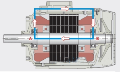
1. Induced voltage along the axis
The induced voltage along the shaft will create a current loop through bearing 1, housing and bearing 2 at the same time, Figure 1. One reason for this type of shaft voltage is due to the uneven distribution of the magnetic flux inside the motor, especially in some motors with a small number of pole pairs. At this time, as long as one end of the bearing is insulated, the current loop can be completely cut off. Normally insulated non-drive end bearing
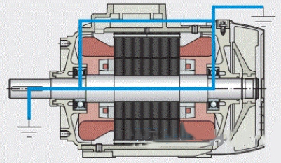
2. Voltage between shaft and bearing seat
If a voltage occurs between the shaft and the bearing housing, current flows through each bearing in the same direction. This is mainly caused by the common mode voltage brought by the inverter. In this case, the bearings at both ends of the motor should be insulated, see Figure 2. The determining factor in the choice of insulation is the time characteristics of the current and voltage. In the case of DC voltage or low-frequency AC voltage, the insulating effect depends on the pure resistance value of the insulating layer; in the case of high-frequency AC voltage (common in equipment using frequency converters), it depends on the capacitive reactance value of the insulating layer.
2. Voltage between shaft and bearing seat
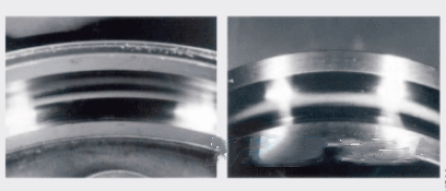
2. Electro-erosion groove marks
The so-called galvanic groove marks refer to the continuous periodic groove marks on the raceway surface in the running direction. Most of these phenomena are caused by the current passing through the bearing, as shown in Figure 4
If a voltage occurs between the shaft and the bearing housing, current flows through each bearing in the same direction. This is mainly caused by the common mode voltage brought by the inverter. In this case, the bearings at both ends of the motor should be insulated, see Figure 2. The determining factor in the choice of insulation is the time characteristics of the current and voltage. In the case of DC voltage or low-frequency AC voltage, the insulating effect depends on the pure resistance value of the insulating layer ; in the case of high-frequency AC voltage (common in equipment using frequency converters), it depends on the capacitive reactance value of the insulating layer.
4. Check the damaged structure of the overcurrent bearing under the microscope
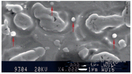
Only through scanning electron microscopy (SEM), we can clearly see that almost all damaged surfaces are densely covered with pits and μm-level solder joints (Figure 5), which also confirms that there is current flowing through the bearing.
Five, the process of bearing damage
The formation of such dimples and welds is caused by electrical discharges that occur between tiny contact points on the raceway and rolling element surfaces. In full-fluid lubrication, the electric current will break down the weak point of the oil film, and the energy generated by the electric spark will melt the surface of the adjacent metal in an instant.
In mixed friction conditions (metal-to-metal contact), adjacent surfaces also fuse, but are quickly separated as the bearing runs. In both cases, material detaches from the metal surface and immediately solidifies into a solder joint. There are also some solder joints that will be mixed with lubricant, and others will be deposited on the raceway surface. As the bearing continues to run, these welds and dimples are also milled flat. Under the action of a continuous current, the above-mentioned melting and solidification process is repeated many times on a very thin layer of adjacent surfaces.
However, on the inside of most galvanic bearings, galvanic grooves are more likely to be found (see Figure 4 above). Periodic marks on raceways and rolling elements of this type are the result of the combined effects of continuous overcurrent and vibration of bearing components. When the rolling element rolls through a sufficiently large pocket, it experiences pure radial displacement, the extent of which depends on the bearing's internal geometry, speed and bearing load. As the rolling elements oscillate back and forth, the thickness of the lubricating oil film changes and more sparks are generated in this area, and this self-excited process is activated. After a period of time, the entire circumference of the raceway of the ferrule is covered with galvanic groove marks. This can cause significant bearing vibrations and eventually lead to the failure of the entire bearing.
It thus shows that a reliable principle for assessing the risk level of bearing overcurrent is to calculate the current density through the bearing, in other words the effective amperage divided by the total contact area of the rolling elements with the inner or outer raceway, respectively. This is related to the type and operating conditions of the bearing. When the current density is less than 0.1 A mm-2, the current passing through according to our current experience will not cause damage to the bearing. However, when the current density is equal to or greater than 1 A mm-2, obvious galvanic groove marks appear inside the bearing.
6. The influence of electric current on lubricant
The passage of electric current can also have a negative effect on the lubricant. The base oil and additives in it are subject to oxidation and cracking. This change can be clearly seen in the infrared spectrum. Premature aging and the accumulation of ferrous metal particles can lead to poor lubricant performance and can also cause the bearing to run too hot.
Zhejiang waxing electromechanical co.LTD.
Copyright © 2025 Zhejiang waxing electromechanical co.LTD. | All Rights Reserved Design
Hello, please leave your name email or WhatsApp here before chat online so that we won't miss your message and contact you smoothly.