CONTACT US
Zhejiang waxing electromechanical co.LTD.,Factory located in Shandong,Headquarters located in Zhejiang,China.
Until all motors are designed with built-in bearing protection, plant maintenance personnel and motor repair shops will continue to replace damaged bearings. But if a motor's bearing problem is fixed correctly and proper mitigation installed, it only has to be done once.
Better yet, informed technicians can make use of the latest diagnostic techniques (vibration analysis, thermography, shaft-voltage testing, etc.) to ward off electrical bearing damage from the beginning. For a new motor or one already in service, this is what is meant by "best practices."
Bearing failure rates vary widely, but evidence suggests that a significant portion of these failures occur only three to 12 months after system startup. Because many of today's motors have sealed bearings to keep out dirt and other contaminants, electrical damage has become the most common cause of bearing failure in AC motors with VFDs.
The high switching frequencies of today's VFDs produce parasitic capacitance between a motor's stator and rotor. By now it is widely understood that once the resulting shaft voltages overcome the dielectric properties of bearing grease, they discharge along the path of least resistance — typically through the bearings (Figure 1).
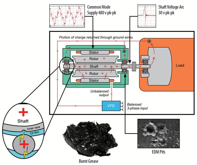
Figure 1. Voltages arcing through the bearings of VFD-driven motors create thousands of pits, which cause increased friction and noise and the potential for costly unplanned downtime as bearing grease deteriorates.
These discharges are so frequent that they create millions of tiny fusion craters. Before long, the entire bearing race wall can become marked with countless pits known as frosting. A phenomenon known as fluting may occur as well, shaping the frosting into washboard-like ridges across the bearing race (Figure 2). This causes noise, vibration, increased friction, and catastrophic bearing failure.
For environments where the motor will be exposed to excessive amounts of dirt, dust, or other debris, it may be necessary to protect the ring's fibers with an O-ring or V-slinger. Bearing isolators with built-in circumferential grounding rings are also available. For severe-duty environments such as many mining applications, however, mounting the shaft grounding ring inside the motor provides the best protection from contamination (Figure 5).
Figure 5. Internal installation of the grounding ring provides extra protection from dust, dirt, and other contaminants in severe-duty applications.
Using conductive epoxy or screws, the ring can be mounted directly to a bearing retainer. An additional machined spacer will keep the ring away from the bearing grease cavity. Metal-to-metal contact is still essential, so the bearing retainer must be free of any coatings or other nonconductive material where it will touch the ring.
For horizontally or vertically mounted motors with the horsepower of 100 or less and single-row radial ball bearings on both ends, a shaft grounding ring can be installed on either end. For horizontally mounted motors with horsepower greater than 100 and single-row radial ball bearings on both ends, the bearing housing at the non-drive end must be electrically isolated to disrupt circulating currents. Options for achieving such isolation include insulated sleeves, nonconductive coatings, ceramic bearings or hybrid bearings. The grounding ring should be installed at the drive end.
For any motor in which the bearings at both ends are already insulated, the drive end is preferred for installation of a grounding ring to protect bearings in attached equipment such as a gearbox, pump, fan, or encoder.
For any motor with cylindrical roller, Babbitt, or sleeve bearings, the end with such bearings should be electrically isolated, and the grounding ring should be installed at the opposite end.
Zhejiang waxing electromechanical co.LTD.
Copyright © 2025 Zhejiang waxing electromechanical co.LTD. | All Rights Reserved Design
Hello, please leave your name email or WhatsApp here before chat online so that we won't miss your message and contact you smoothly.