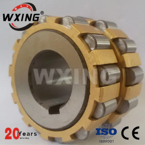
To solve the problem as shown in figure 1 in spherical bearing processing, we design and manufacture of the boring bar is shown in figure 2, installed on a lathe, solved with general equipment manufacturing and the key technology of the bearing.
(
img]
200906/20090605152149.
jpg [
/img]
Boring bar 1 with three jaw chuck clamping and special top 15 bearing, tool rod 3 4 installed in the boring bar with axis 1 long groove, one end of the clip fixed cutter 5, on the other side through the pin shaft 2 connected with connecting rod (6).
Connecting rod 6 at the other end through the pin shaft connected to the nut 8 7.
Turn the screw 9, can make the nut 8 in the dovetail groove of the boring bar 1 move.
T20×1。
5 the left-hand screw 9 in 10 hole in the rotation.
Watts 10 from 16 fastening bolt in the boring bar 1 right end.
Gear 11 (
m = 2;
z=31;
x=-
0.
5)
Through the flat key 12, washer, 13, 14 on the screw nut 9 right end.
Boring bar 1 rotates, gear 11 special top 15 rotate.
Top 15 milling m = 2;
z = 12;
x = 0。
5 teeth, so gear rotates, 11 to 9 screw rotates, making silk mother 8 on the boring bar through the pin 7, 6 connecting rod, pin shaft drives the cutter bar 3 and 2, centered on shaft 4 bit 5 in the long groove of boring bar about arc movement, thus accomplishes the processing within the sphere.
Operation method: the workpiece fastening on the lathe big slide board, with ordinary boring bar first boring & Oslash;
164 on both sides of inner hole and end face, then use 1 boring boring bar within the sphere.
According to the machining allowance and ball face turning depth, determine 5 stretched out the length of the cutting tools, with screw fastening of the cutting tools.
Mobile slip plate parts center on is the center of the shaft 4, tighten the big slide plate.
Turn head spindle are five axis four driving rotation from right to left, start cutting boring a knife after parking, shaking big slide plate to move artifacts operation lever, loosen the fastening screw, remove the cutting head, flipping over (
The knife before facing down)
Again in the tool bar, and make out is equivalent to a certain depth of the turning of the cutting tools, tighten cutting head, to roll back the big slide plate fastening good, open the car, then start from left to right rotation of the cutting tools and cutting, repeated several times, until the processing to the appropriate size.
Recommended when rough boring.
Tool main Angle f and vice are 45 ° Angle f1, point to grinding into fine boring with R95 ~ R100 arc blade, in order to improve the surface quality.
(
img]
200906/20090605152241.
jpg [
/img]
1.
Boring rod 2.
The pin shaft 3.
Tool rod 4.
5.
Six of the cutting tools.
Connecting rod 7.
Pin 8.
Silk mother 9.
Screw 10.
11.
Gear 12.
Flat key 13.
14 of the gasket.
Nut 15.
Special top 16.
Figure 2 bolts