Effects of mill gear mesh size and set-up of experience
by:Waxing2020-11-14
Effects of mill gear mesh size and calibration experience - 2021
01 -
21 Zhang Sheng (
Deyang golden star cement company)
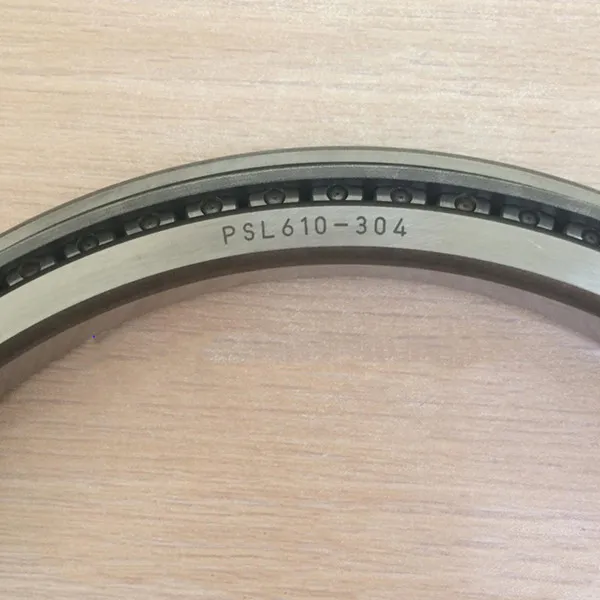
Mill because of improper installation or use maintenance transmission system is unusual, need to adjust the size of the gear meshing, at this time if only considering the size of tip clearance and side clearance of the gear mesh is too limited, should consider the whole mill system there may be a problem.
In this paper, the influence factors of gear mesh size and set-up a summary.
A small gear, the influence of pinion basis if the foundation to loosen, you must hit the second pouring concrete layer, check whether shim layout specifications, stress is uniform,
Can pass feeler check)
。
And specification again mat iron, using optical level coordinate frame level to find spur pinion.
Second, the influence of the cylinder levelness set-up a phenomenon is just blindly pursue pinion to motor to drive the level of accuracy.
But due to factors such as uneven subsidence, caused by mill on both ends of the main bearing alignment error is too big, at this point, the axis of the mill big gear and small gear may be able to adjust the parallel, but delay to put to the axis of the gear reducer, motor cross will appear deviation, then only set-up gear cannot fundamentally solve the problem, need to detect and adjust the levelness of the cylinder.
Barrel level measurement method: check appliances using saddle iron plus optical level, 1000 mm vernier caliper and a 150 mm frame level.
Optical level is placed in the central cylinder, put the saddle iron respectively at the ends of the cylinder processing radial plane (
Is the check cylinder and the main bearing connection mouth, survey points to use electric steel brush to clean up first)
, first the saddle with box type level iron levels, and then put the vernier caliper on the saddle of iron.
Comparing with optical level read two points difference.
Three, the influence of the big gear screen big ring gear and the wheel hub connecting bolts, if loose, tighten again after to clean the joint surface, and then use two dial indicator (
Or dial gauge measuring large gear ring radial and transverse jitter values and recorded, adjustment to provide data for the next step.
In general most face runout after heat treatment the parts machining has been controlled.
If face runout overrun, tend to be caused in the installation, failed to close with the big gear ring of wheel hub with the big gear ring end face for processing, such as debris, transportation or loading and unloading at the time of the collision and scratches, and so on.
Reasonable approach is to replace the big gear ring, if continue to use the big gear ring, then in the tip clearance time will increase (numerical control
Actual radial runout numerical largest permissible radial runout on the manual number)
。
Four, the size of the adjustment of the gear mesh method first check whether the pinion installation Angle is conform to the requirements of the drawings, using frame level is roughly tuned the pinion.
The size of the gear meshing clearance and tip clearance control two, the new gear, two control are applicable, but the old gears, tooth surface uneven wear, two tooth meshing clearance is not a set of approximate data, no reference significance.
Therefore, USES the method to control the tip clearance, the error of gear wear as possible eliminate, only consider between bidentate full contact, with 0.
02 mm feeler respectively into the ends of the meshing teeth, artificial use tools to combine the two teeth, by adjusting the tilting pad iron, feeler at both ends to pull out as criterion, finally will mat iron weld, in each group to secondary pouring.
Tip clearance values for dx = 0.
25m+jt+rz(
Type: dx for headspace, m as the modulus, jt for radial runout, rz for thermal expansion amount, rz generally in 1.
Values between 5 ~ 3 mm, raw meal grinding or relief grinding can remove the limit, cement mill take upper limit)
。
The above control don't have to consider the size of the lateral clearance, which can fully guarantee the two teeth meshing surface contact state, guarantee the gear stress in reasonable condition.
Five, the calibration coupling method to complete the main transmission part of the cylinder to the pinion leveling adjusted, adjustment to the direction of the pinion to motor.
In the process of adjusting coupling, must not use 'will dial indicator on the body and a half, probe to touch the other a half body motionless method' to seek alignment, because this method is suitable for parts of equipment manufacture stylish look is leveling, not suitable for old equipment.
Because after the operation of the mill (
Including the mill after installation)
, are all more or less on the coupling surface scars, inevitable form and position tolerances, great error of data obtained from the above methods.
The right thing to do is to 30% ~ 50% of the two coupling assembly fittings (
Shaft pin or shaft block)
The two dial indicator, in one and a half body is 90 ℃ Angle on the two points of measuring head onto the other half body, one of the measuring head at half body of radial circular beating value, another measure in the end of the radius of a head or shoulder for face runout value, use artificial auxiliary let two and a half body synchronous rotation.
This approach because the relative movement between the basis point and measurement point can only be caused by the alignment error, and the geometric error of object to be tested will not affect the result of the measurement.
Six, the influence of the bearing in the processing speed reducer parts must adjust bearing clearance and freedom, otherwise will lead to the sound of reducer, bearing high temperature, etc.
(
Source: China cement spare parts network)